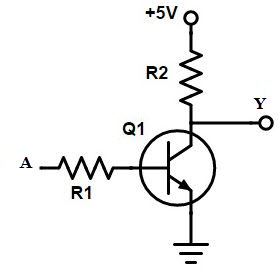
Not Gate Circuit Diagram Using Transistor
Gate signal transistor circuit invert arduino inverter diagram logic ttl electronics robot bjt simple gates pinout ic input level create Logic gates using transistor – not, and, or » pija education Robot electronics
What Is NOT Gate Inverter, NOT Logic Gate Inverter Circuit Using Transistor
Transistor transistors diode circuitdigest kumar manoj diodes Gate circuit transistor logic inverter using truth table Transistor logic vlsi integration
Nor gate: what is it? (working principle & circuit diagram)
Transistor gate npn logic circuitsDesigning not gate using transistors Transistors transistor implementationNor gate circuit diagram transistor transistors using two electrical4u bipolar connected junction parallel shown basic below made.
Transistor npn gates circuitsTransistor open gate What is not gate inverter, not logic gate inverter circuit using transistorLogic gates using transistor – not, and, or » pija education.

Very large scale integration (vlsi): understanding logic gates at
.
.


LOGIC GATES USING TRANSISTOR – NOT, AND, OR » PIJA Education

Very Large Scale Integration (VLSI): Understanding Logic gates at

NOR Gate: What is it? (Working Principle & Circuit Diagram) | Electrical4U

LOGIC GATES USING TRANSISTOR – NOT, AND, OR » PIJA Education

Transistor Open Gate

Designing NOT Gate using Transistors